Interesting Science Videos
List of 16 types of microscopes
- Simple Microscope
- Compound Microscope
- Phase Contrast Microscope
- Fluorescence Microscope
- Electron Microscope
- Scanning Electron Microscope (SEM)
- Transmission Electron Microscope (TEM)
- Dark Field Microscope
- Dissecting Microscope (Stereo Microscope)
- Digital Microscope
- Scanning Probe Microscope (SPM)
- Atomic Force Microscope (ATM)
- Inverted Microscope
- Acoustic Microscope
- X-Ray Microscope
- Polarizing Microscope
- Metallurgical Microscope
- Pocket Microscope
- USB Microscope
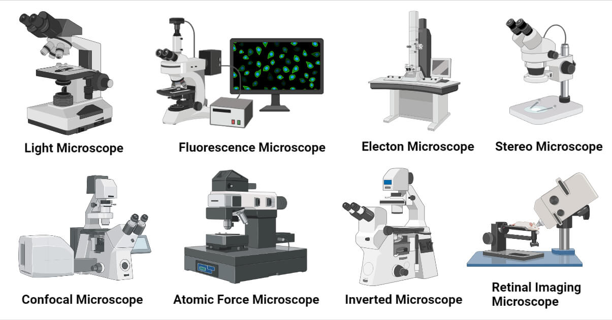
1. Simple Microscope
A simple microscope is a type of microscope that uses a single lens for magnification. It uses a single convex lens of a small focal length for magnification. In general, its magnification is about 10X. Its magnifying power (m) is given by;
m=1+ D/F
where,
D = least distance of distinct vision
F = focal length of the lens of a microscope
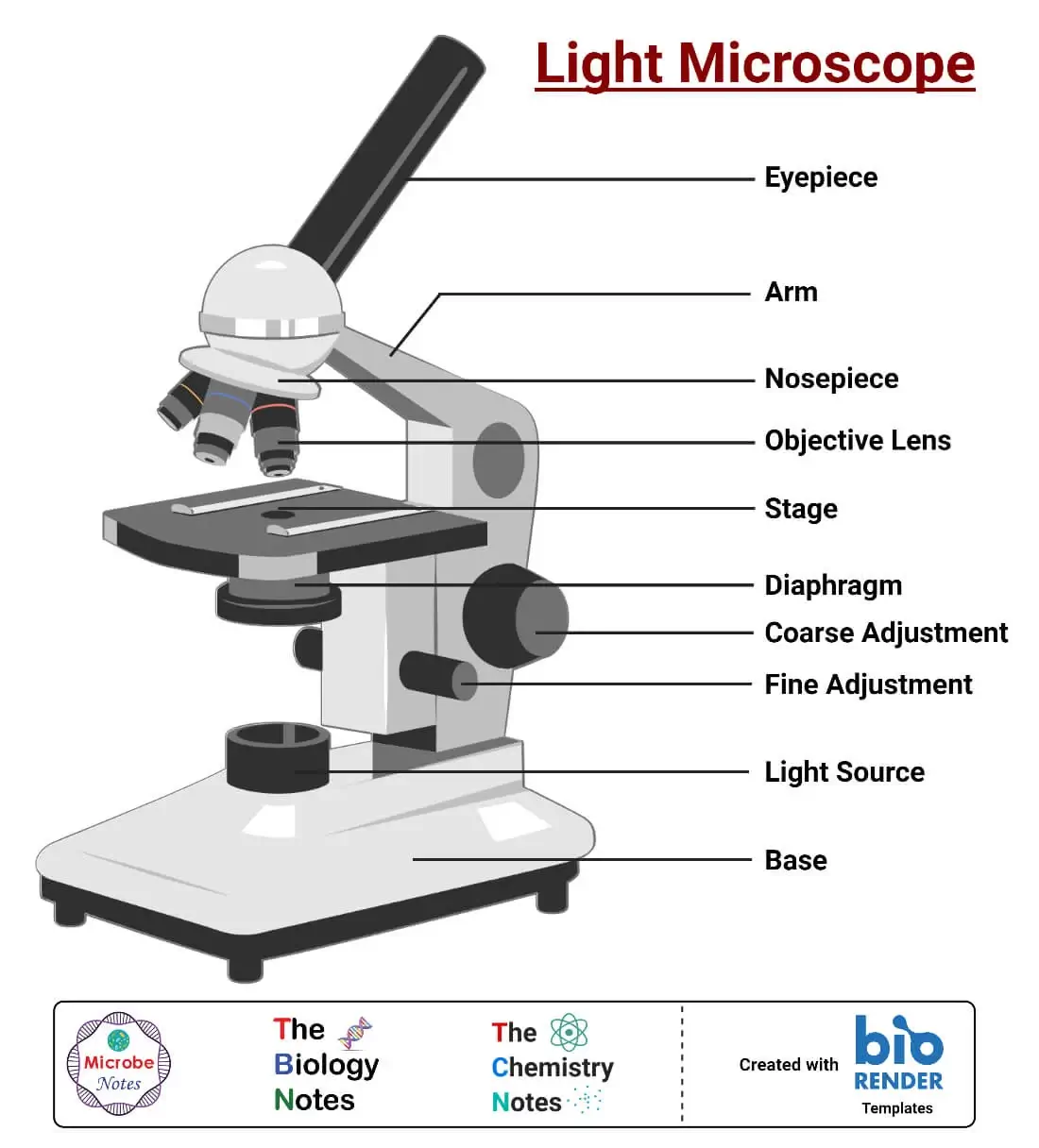
Simple Microscope Working Principle
when a sample is placed in the focus of the convex lens of a microscope, a virtual, erect, and magnified image is formed at the least distance of the distinct vision. Parts of a simple microscope; mirror as illuminator, convex lens for magnification, stage and metallic stand with base.
Uses of Simple Microscope
- Used to study morphology of insects, algae, and fungi
- Used in studying soil type and components
- Used in electronic repairing workshops for repairing watches, mobile phones and other micro devices and components
- Used by jewelers to check quality of diamonds, rubies and other gem stones
- Used to study details of engravings, scripts with smaller letters, etc.
Limitation of Simple Microscope
- Have very low magnification; upto 10X
- Mirror for illumination and lack of mechanical stage
- Require thin stained specimen for clear vision
- Very low resolution and image contrast
2. Compound Microscope
Compound Microscope is a type of microscope that used visible light for illumination and multiple lenses system for magnification of specimen. Generally, it consists of two lenses; objective lens and ocular lens. It can magnify images up to 1000X. Its magnifying power is equal to the product of magnifying power of the objective lens in use and the ocular lens. Mathematically it is expressed as;
m= D/f0 x L/fe
where,
m = magnifying power
D = least distance of distinct vision
L = length of the tube
fe = focal length of the ocular lens
f0 = focal length of objective lens
It is the most widely used microscope in biological fields like medicine, microbiology, life-sciences, pathology, hematology, anatomy, molecular biology, etc.
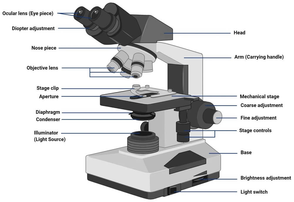
Compound Microscope Working Principle
When light is focused through a condenser on a specimen placed on stage, the light transmitted by the specimen is picked by the objective lens. A magnified image is formed at the body tube. This is called the primary image. The light bends in the body tube and passes through the ocular lens. When passing through the ocular lens, the image is magnified for the second time. This is called the secondary image. Finally, a highly double magnified image is formed at a distance of distinct vision.
Compound Microscope Parts
- Illuminator (Light Source)
- Diaphragm (Iris)
- Condenser
- Condenser Focus Knob
- Rack Stop
- Stage
- Stage Control Knobs
- Nose Piece
- Objective Lens
- Tube (Head)
- Eyepiece (Ocular Lens)
- Diopter Adjustment
- Adjustment Knobs
a. Fine Adjustment Knob
b. Coarse Adjustment Knob - Arm
- Base
- Light Switch
- Brightness Adjustment
Uses of Compound Microscope
- Used in microbiology to study the morphology of microorganisms
- Used in histopathology to study tissue, cytopathic effects, tumor, etc.
- Used in cytology to study cellular structure of different types of cells
- Used by biologist to observe slides of cells, tissues or segments of biological components
Limitations of Compound Microscope
- Can’t produce image of objects smaller than wavelength of visible light (0.4 μm)
- Has lower resolution and image contrast
- Can’t be used to view living internal structures
- Require thin, and stained specimen
3. Phase Contrast Microscope
Phase Contrast Microscope is an optical microscope that converts small phase shifts in light into differences in light intensity developing more contrast in images that can be easily detected by human eyes. When light passes through transparent specimens a small phase shift occurs which can’t be detected by our eyes. Using phase plates, these small phase shifts are converted to changes in the amplitude of light. This change in amplitude can be observed as differences in image contrast.
It can be used for observing living cells in their natural state without staining or fixing. Transparent specimens and subcellular organelles can be clearly viewed with better contrast.
Due to the difference in thickness and refractive index of different parts of a specimen, a small phase shift in light rays occurs when the light passes through the specimens. This phase shift can be changed into differences in light intensity (brightness) which will produce more contrast in the image.
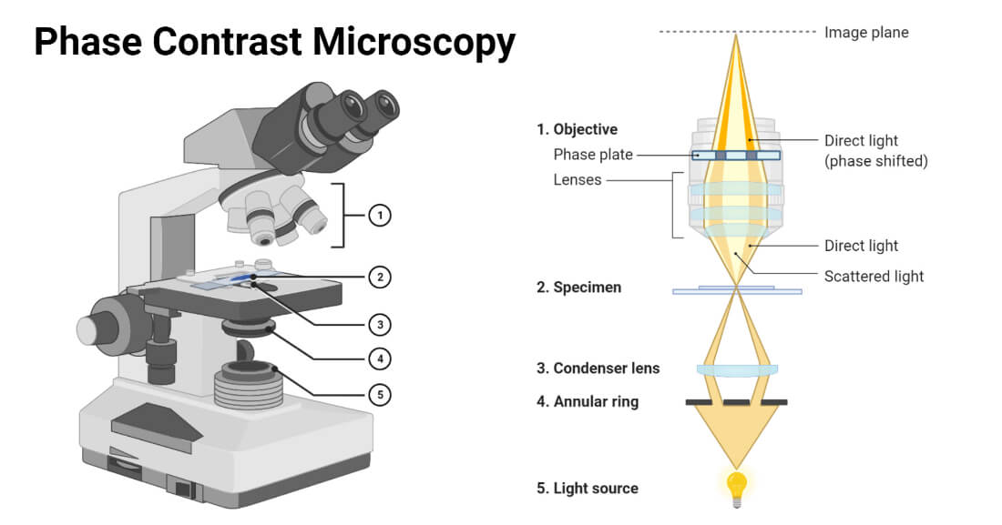
Phase Contrast Microscope Principle
Light from the illuminator is focused on the specimen through the condenser annulus. This light passes through different regions of the specimen having different refractive indexes and thicknesses. The light rays that pass through an area of higher refractive index and thickness, will experience larger phase retardation than those rays passing through an area of lower refractive index and thickness. These phase shifts are undetectable to the normal human eye. An optical device like a phase plate converts these phase shifts into brightness change which creates observable contrast differences in the final image.
Phase Contrast Microscope Parts
It contains all the parts of a compound microscope, and additionally contains two optical parts, condenser annulus, and phase plate, for phase contrast.
- Condenser Annulus
It is also called phase condenser or sub-stage annular diaphragm. It is an optical part that focuses a narrow hollow cone of a light beam on a specimen to be observed.
It is a black (light-absorbing) circular plate with a transparent annular ring/groove. The light passed through the annular ring and fall on the specimen placed on the stage. In a microscope, it is placed below the condenser.
- Phase Plate
It is another optical part that selectively alters the phase and amplitude of light coming from the specimen. It is placed above the objective rear focal plane.
It is a circular transparent plate whose surface can be divided into two portions. The portion upon which the condenser annulus is focused is termed the conjugate area. The remaining portion is collectively called a complementary area.
The complementary area is coated with light retarding material like magnesium fluoride.
The phase plate is of two types; a positive phase plate having a thinner conjugate area, and a negative phase plate having a thicker conjugate area.
Uses of Phase Contrast Microscope
- Observing living cells in its natural form
- Used in microbiology to observe protozoans, diatoms, planktons, cysts, helminths and larvae.
- Used to study subcellular structures and cellular processes
- Used to study thin tissue slices
- Used to study lithographic pattern and latex dispersion, glass fragments and crystals.
Limitations of Phase Contrast Microscope
- Not ideal for thick specimen
- Halo effect and shade-off are common
- Condenser annulus limit the aperture, hence decrease resolution
4. Fluorescence Microscope
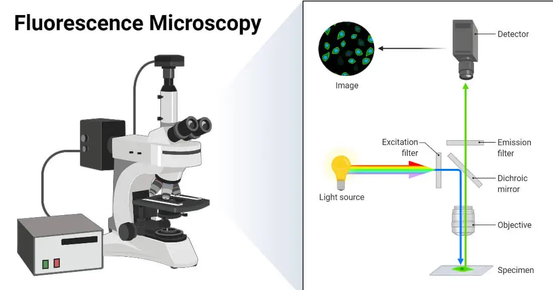
Fluorescence Microscope is an optical microscope that uses fluorescence or phosphorescence to generate an enlarged image of a specimen. It is a modified light microscope. This microscope can be used to study living cells and cell organelles, identify specific proteins, antigens and immunoglobulin. They have very high sensitivity.
Fluorescence Microscope Principle
It works on the principle of fluorescence. When monochromatic light is passed on an object stained with a fluorophore, it re-emits the light. The emitted light is detected to form an enlarged image of the specimen.
The specimen is stained with a fluorophore and placed on the stage. High energy light is generated and passed through an excitation filter. This filter allows only the light of a particular short wavelength (UV region) capable of exciting the fluorescent molecule to pass through and block all other wavelength light.
The filtered light is reflected to the sample using a dichroic filter. The fluorophore absorbs the light rays which cause the electron to excite in a higher energy state. The excited electrons return to the ground state releasing the excited energy in form of light rays with a longer wavelength.
The emitted light passes through the dichroic mirror and hits the emission filter. This filter blocks the short-wavelength light and allows longer wavelength light to pass through ocular lenses to a detector system.
In the detector, an enlarged image is formed. The background is observed as dark and the image appears as bright.
Fluorescence Microscope Parts
A typical fluorescence microscope contains the following parts;
- Fluorophore (Fluorescent Dye)
These are the chemical compounds that possess the property of fluorescence i.e. re-emit the light upon excitation by light. These are combinations of several aromatic or planar compounds with several pi (π) bonds. Most of them are organic compounds. They stain a wide range of biomolecules and cellular structures. Some common fluorophores used are fluorescein, rhodamine, cyanine, antraquinone, acridine orange, acridine yellow, auramine, malachite green, etc.
- Light Source
Commonly mercury vapor lamp is used for generating UV light. Besides, xenon arc lamps, high-power LEDs, and lasers are also used. They emit the light of high energy.
- Excitation Filter
It is a band-pass filter that allows the light of a short wavelength that can excite the fluorophore to pass through and block all other exciting and long-wavelength radiations. They are placed in an illumination path i.e. in the path before the specimen.
- Emission Filter
It is another band-pass filter that allows all the fluorophore emitted light to pass through and block all other light in the excitation range. They are placed in the imaging path i.e. in the path after the specimen. This ensures the darkest possible background and a brighter image with high contrast.
- Dichroic Mirror (Beam Splitter)
It is a special mirror that selectively reflects or transmits the light of a specific wavelength. It is positioned in between the excitation filter and emission filter at an angle of 45°. It reflects the light from the excitation filter to the fluorophore and transmits the emitted light to the emission filter.
- Others
It contains a detector system, objective lenses, ocular lenses, and all other parts of a compound microscope.
Types of Fluorescence Microscope
There are different types of fluorescence microscopes. Some common types are;
- Epifluorescence Microscope
Epifluorescence Microscope is the most common type of fluorescence microscope. In this type, the excitation of fluorophore and detection of the fluorescence are done through the same light path i.e. exciting light and emitted light both passes through an objective lens.
- Confocal Microscope
Confocal Microscope is a microscope that uses a spatial pinhole to block out-of-focus light and uses only light from the plane of focus to develop a 3-D image with higher resolution and image contrast. It is also called a confocal laser scanning microscope.
It is a type of fluorescence microscope that is used to produce 2-D or 3-D images of relatively thick specimens. In this type, the excitation light is focused on a specific spot of sample lying on the focal plane. The focus spot is optically manipulated to scan the entire sample and generate a 3-D image. A high-resolution image with better contrast is obtained.
This type of microscope uses laser light for illumination. The use of a confocal aperture and oscillating mirror made it possible to focus the laser light on a particular spot. They neglect the background noise from unfocused spots and prevent fast photo-bleaching and light scattering.
It is based on the optical sectioning technique where multiple 2-D images are combined to form a 3-D image.
Laser light is used for illumination. Laser is passed over the fluorophore stained sample. The emitted fluorescent light is passed through a pinhole located in the optical path. It selectively allows emitted light from the focused point to pass blocking all other background lights. The light is converted to an electrical signal by a photomultiplier tube. Computer software analyzes the electrical signal and produces a 3-D image.
Confocal Microscope Applications
- Used for detecting eye corneal diseases and fungal cells in corneal scrapings
- Used in quality control of pharma products
- Used in optical 3-D scanning and imaging
Confocal Microscope Limitations
- Limited excitation wavelength and narrow bands
- Expensive system
- Multiphoton Microscope
It is a type of fluorescence microscope that uses more than one photon for exciting fluorophore molecules. The multiphoton fluorescence excitation results in a high-resolution 3-D image. The most common types are two-photon and three-photon excitation microscopy.
- Total Internal Reflection Fluorescence (TIRF) Microscope
It is a type of fluorescence microscope that is used for selectively imaging fluorophore molecules in an aqueous environment close to a solid surface with a high refractive index. High-resolution images with better contrast decreased background and brighter clearer images are its advantages.
Uses of Fluorescence Microscope
- Study structure of fixed and live cells and cell organelles
- Used to measure physiological state of cells
- Detection of acid fast bacteria, malarial parasites and other microorganisms in clinical samples
- Used in immunology and biochemistry to study macromolecules and nucleic acids
- Used in Fluorescent In-situ Hybridization (FISH) technique in study of microbial ecology
Limitations of Fluorescence Microscope
- Photo-bleaching limits the time interval for observation of specimen
- Phototoxic effects of fluorophore
- Need of specific fluorophore for staining specific structures
5. Electron Microscope
Electron Microscope is a microscope that uses accelerated electron, beams instead of light rays, to illuminate the specimen and get the highly magnified image. In this microscope, glass lenses are replaced by electromagnets. Due to the very short wavelength of electrons, this microscope produces a very high-resolution image with magnification up to 10,000,000X. Very high-quality images with very high contrast, revealing detailed structures are produced. Specimen up to 0.2 nm can be clearly viewed using an electron microscope.
Electron Microscope Principle
An electron microscope uses accelerated electrons with a wavelength of about 100,000 times shorter than visible light to illuminate specimens and produce images. The electron gun, usually a heated tungsten or field emission filament, is used to generate a stream of high voltage (100 – 1000 kV) electrons. These electrons are accelerated using an anode plate in a vacuum system and focused on the specimen using aperture and electromagnetic lenses.
The electron beam passes through the specimen and interacts with sample components. Upon striking the specimen, the electrons are scattered. The degree of scattering depends on the refractive index or thickness of the specimen.
The scattered electrons from the sample are collected and passed through objective and ocular electromagnetic lenses. These scattered beams are detected and transformed into highly magnified images by the magnetic lenses.
Electron Microscope Parts
A typical electron microscope has the following parts;
- Electron Gun (Electron Source)
It is a device that generates electron beams for specimen illumination. It contains a cathode and an anode. The cathode is generally a tungsten filament. When the tungsten filament is heated using a high voltage current in a vacuum, electrons are released.
A negative cap around the filament confines the released electrons into a focused electron beam, which gets accelerated by the positive anode towards the specimen.
- Electromagnetic Lenses
Unlike light microscopes which use glass lenses for magnification, the electron microscope uses magnetic fields generated by magnetic coils (electromagnets). This type of lens allows electrons of specific energy to pass through and block other electrons. There are three types of electromagnetic lenses;
- Condenser lens, which focuses the accelerated electron beam on the specimen as a thin and tight beam.
- Objective lens, which collects the electron beam coming out of specimen after interaction and bends them to magnify the image.
- Projector (ocular) lens, which further magnify the image generated by objective lenses.
- Aperture System
These are pinholes that filter the unwanted electrons from the electron beam before and after hitting the specimen. This system contains thin disks with a microscopic hole of 2 – 100 μm diameters. There are two apertures, a condenser aperture below the condenser lens, and an objective aperture in between objective and projector lenses.
- Sample Holder
It is a platform with a mechanical arm for holding and positioning specimens in a fixed position. It is made up of extremely thin carbon film held by a metal grid.
- Vacuum System
The entire lenses, aperture, sample holder, and specimens are arranged in a closed vacuum column. Highly effective vacuum pumps are used to maintain the vacuum. The vacuum allows electrons to generate and travel without colliding and scattering from their path.
- Imaging System
This system includes electromagnetic lenses for refocusing, enlarging, and projecting images, a screen for image development, and a camera for image recording and display. The screen is usually a phosphorescent plate that glows when gets stroke by electrons. The final image formed is called an electron micrograph, and is displayed on a phosphorescent plate or on a monitor.
Types of Electron Microscope
There are different types of electron microscopes of which, TEM and SEM are the most commonly used and important types. Some common types of electron microscopes are;
- Transmission Electron Microscope (TEM)
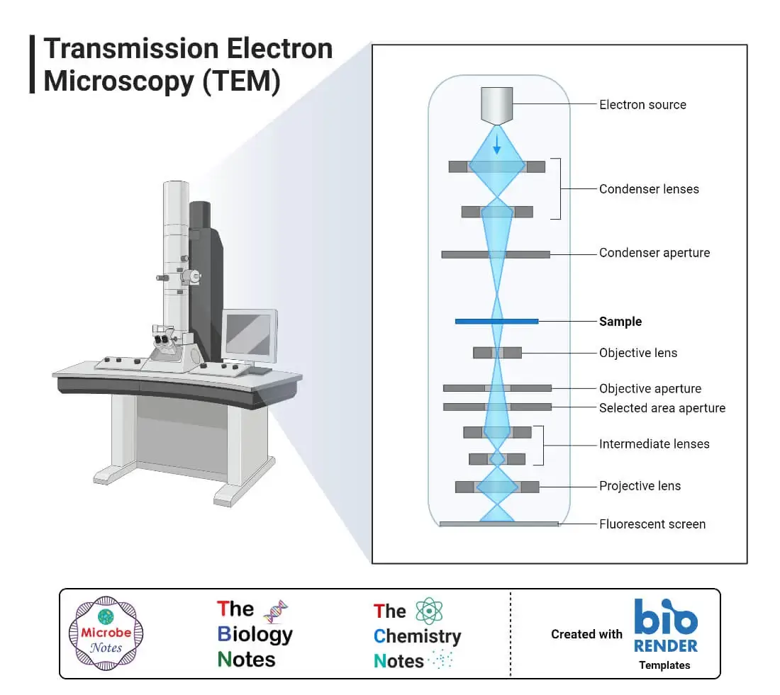
Transmission Electron Microscope (TEM) is a type of electron microscope that uses transmitted electrons to develop an enlarged image of a specimen.
In this system, very thin specimens, not more than 100 nm (about 200 times thinner than specimens used in the compound microscope), are used. Electrons are focused on the specimen using a condenser lens. The electrons interact with components of the specimen and get emitted out from the sample. The emitted electrons are passed through objective and ocular electromagnetic lenses and projected on a fluorescent screen. When the electrons hit the fluorescent screen, an enlarged image is developed.
It is the most commonly used electron microscope. It produces 2-D, black and white images with very high resolution and magnification of 2 to 50,000X.
- Scanning Electron Microscope (SEM)
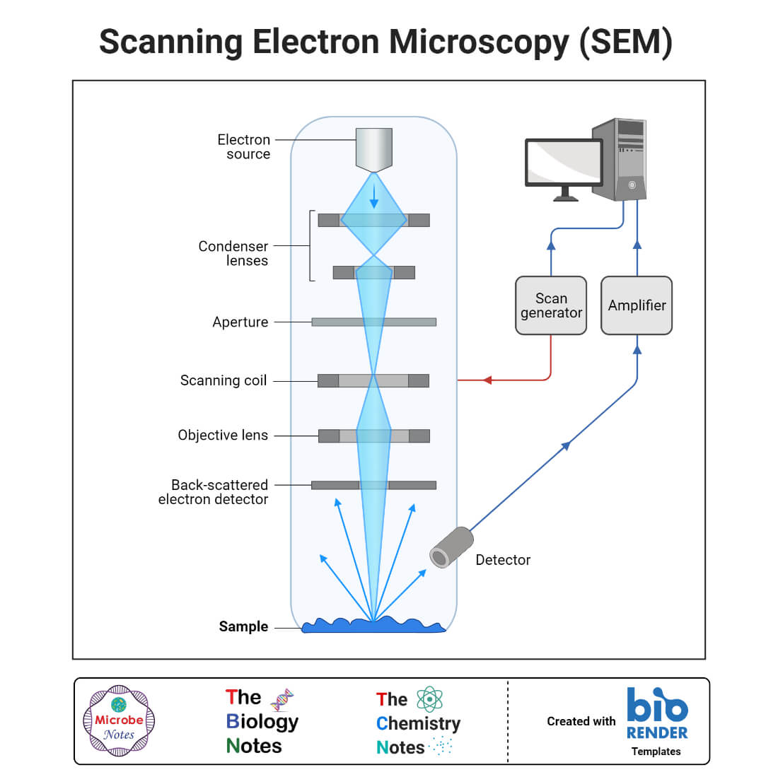
Scanning Electron Microscope (SEM) is a type of electron microscope that scans a specimen with a high-energy beam of electrons in a raster scanning pattern and develops a highly magnified 3-D image of the specimen.
The SEM uses emitted, backscattered, and diffracted electrons for developing images reflecting the characteristic morphological features of the specimen. Although it has less magnification power than TEM, the image will be of higher resolution and sharper.
SEM contains some additional detector instruments like back-scattered electron detectors, secondary electron detectors, and X-ray detectors.
Scanning Electron Microscope (SEM) vs Transmission Electron Microscope (TEM)
| Scanning Electron Microscope (SEM) | Transmission Electron Microscope (TEM) |
| Its imaging is based on emitted and scattered electrons. | Its imaging is based on transmitted electrons. |
| It produces a 3-D image. | It produces a 2-D image. |
| It provides information about morphology and topography. | It provides information about morphology only. |
| A thicker sample can be processed. | Need a very thin sample. |
| It can resolve objects as close as 20 nm. | It can resolve objects as close as 1nm. |
| Comparatively lower magnification, up to 50,000X. | Higher magnification, upto 2,000,000X. |
- Reflection Electron Microscope (REM)
It is the electron microscope that uses the reflected beams of scattered electrons to develop an image. It is a combination of diffraction, imaging, and spectroscopy technique.
- Scanning Transmission Electron Microscope (STEM)
It is an electron microscope that combines SEM and TEM technology to develop an image.
- Scanning Tunneling Microscope (STM)
It is an electron microscope used to reveal atomic and molecular details of specimen surfaces using a phenomenon of tunneling electrons. Rather than penetrating the specimen and imaging the details of the specimen, only the atoms on the surface of the specimen are scanned and projected as 3-D images.
Uses of Electron Microscope
- Used in microbiology to study structure of viruses, flagella, pili, and bacterial cells.
- Used in crystallography, and nano-technology
- To study morphology of cellular organelles
- Used in forensics for ballistic study of gunshots
- Used in geology for studying rocks, minerals and gems
- Used in quality control, detection of fracture and cracks, drug development and analysis of atomic structure.
Limitations of Electron Microscope
- Highly expensive and complex system
- Images are in black and white
- TEM requires very thin specimen
- Need of vacuum system
6. Dark Field Microscope
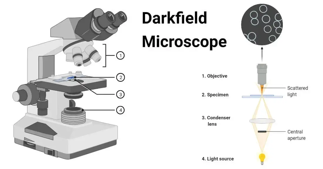
Dark Field Microscope is a type of light microscope that uses only the light scattered by the specimen for producing a bright image with a darkfield around the specimen. It is a modified light microscope that uses an extra opaque disc below the condenser lens which blocks the light coming from the source to reach the objective lens.
This microscope produces a higher resolution and better contrast than a bright field microscope. There is no need to stain the specimens.
Uses of Dark Field Microscope
- Used in microbiology to observe microbial motility, and spirochetes and other very thin bacteria.
- Used to study capsulated organisms
- Used in cytology to study internal organelles
- Used in computer mouse to allow the mouse to work over transparent medium
- It is coupled with hyperspectral imaging for characterizing nano particles
Limitations of Dark Field Microscope
- Any contaminants like dust particles can scatter light giving false image
- Thin spreading of sample is mandatory
- Samples must be wet and moist and strongly illuminated
7. Dissecting Microscope (Stereo Microscope)
Dissecting Microscope or Stereo Microscope is a type of light microscope that uses lights reflected from the surface of a specimen to produce an image of low magnification. It is primarily used during dissecting and viewing dissected specimens, hence called dissecting microscope. This microscope can view 3-D objects, unlike other light microscopes that view slide-fixed objects.
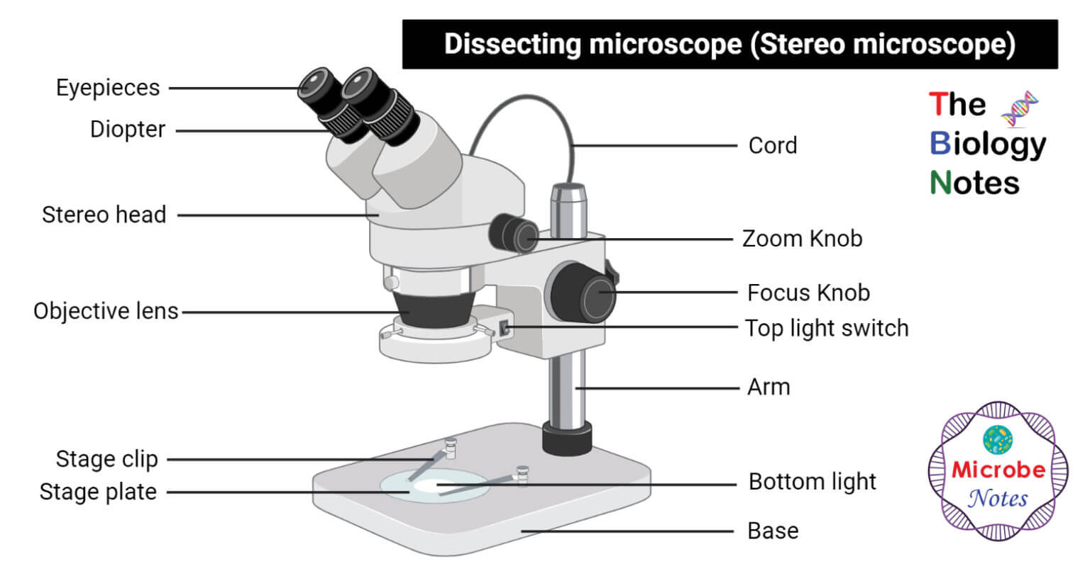
Dissecting Microscope or Stereo Microscope Principle
A stereo microscope uses two ocular lenses which focus on two different light paths and produce a stereoscopic image. They have top light used for dissecting and bottom light used for viewing. Objective lenses of a stereo microscope are inside the cylindrical cone and hence can’t be viewed like in compound light microscopes. The stage is also larger than a usual compound microscope. Usually, there is a groove to prevent the sample from moving.
Uses of Dissecting Microscope or Stereo Microscope
- They are used in dissecting and micro-surgery procedure
- Examining archaeological artifacts and geological samples
- Used in nano electric appliance manufacture and repairing like watches, microchips, mobile phones, circuit boards, etc.
Limitations of Dissecting Microscope or Stereo Microscope
- Has limited use
- Low magnification
- Costly system
8. Digital Microscope
Digital Microscope is a type of microscope that lack an ocular lens and instead contains a digital camera and screen to display image digitally. This is a modern microscope which is a computerized system combining microscope with camera, monitor and computer software, and processor.
The image or video of a specimen can be captured and edited or shared. The software can perform different analyses on the specimen like measuring size, magnifying, and focusing on specific details as well as color correction and editing.
Besides the general parts of a compound microscope, it used a camera replacing eyepieces and an additional display system.
The computer may be inbuilt or externally connected to operate the camera and image processing software system. They can project 2-D and 3-D images. The software allows color contrast, brightness control, graphic and video recording and sharing, and other manipulation of images.
Applications of Digital Microscope
They are being used in several fields including microbiology, pathology, cytology, surgical procedures, nanotechnology, forensics, industrial sectors, etc. They are used in place of compound microscopes because of their image processing and displaying capability.
9. Scanning Probe Microscope (SPM)
Scanning Probe Microscope (SPM) is a type of microscope that uses a scanning probe to scan the surface of the specimen and record the interaction to develop an image. It projects the details of surface atoms and molecules.
It includes Scanning Tunneling microscopes, Atomic Force microscopes, Fluid Field microscopes, Scanning Electrochemical Microscopy, Scanning Thermal microscopes, etc. Atomic force field and scanning tunneling microscope are mostly used type.
9.1 Atomic Force Microscope (ATM)
Atomic Force Microscope (ATM) is a type of scanning probe microscope that uses the repulsive electronic force between the microscope probe tip and surface of the specimen to scan the atoms at the surface of the specimen. It is also called a scanning force microscope.
It can measure properties of specimens like height, friction, and magnetism. The image will be very precise and resolution can be determined in millimeters. It gives a 3-D image. It can also be used for imaging living elements.
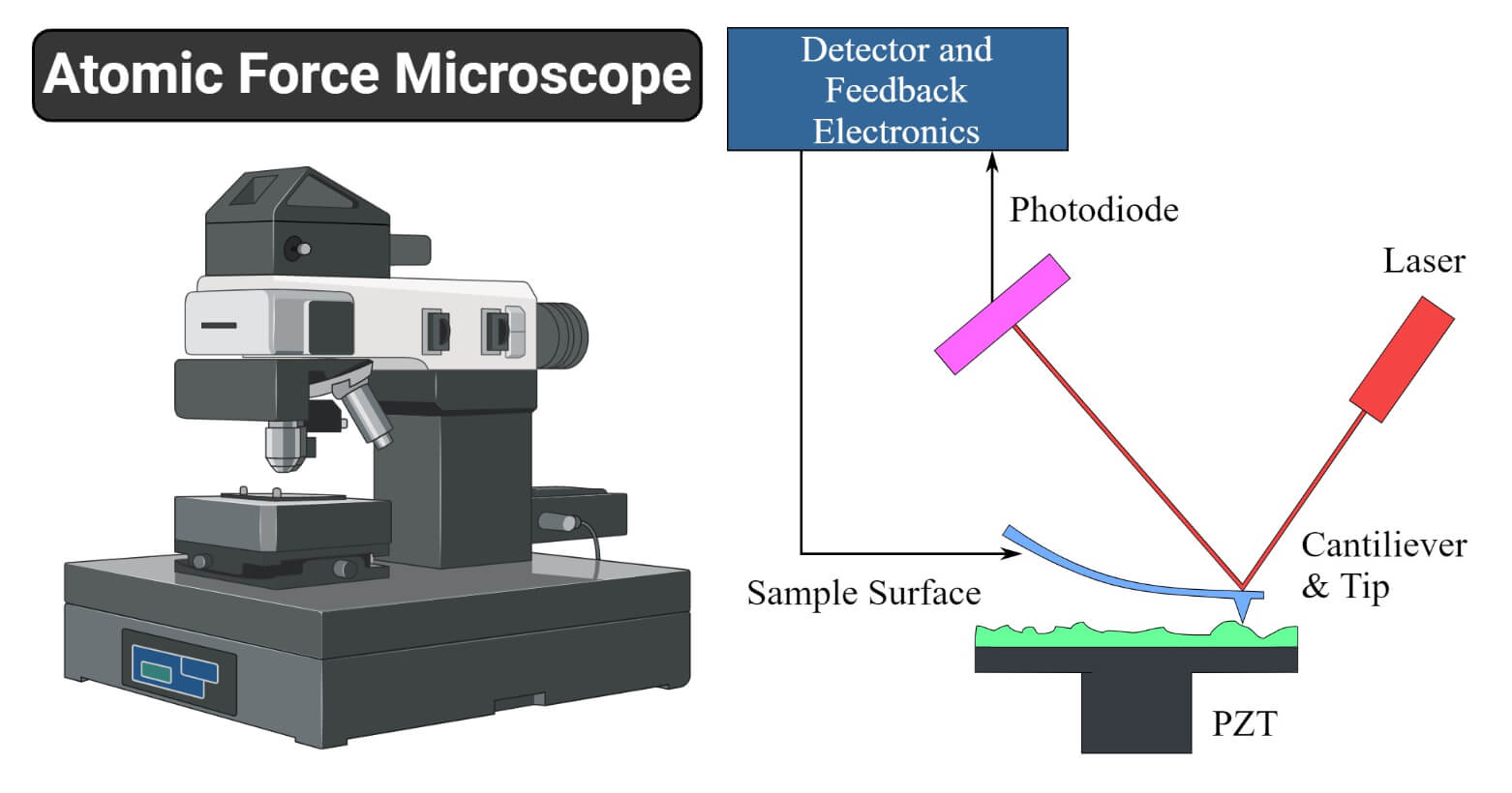
Atomic Force Microscope (ATM) Principle
It works by measuring intermolecular forces and observing surface atoms by using a scanning probe. It functions on the basis of its three major abilities; surface sensing, detecting surface, and imaging.
It performs surface sensing by using a cantilever. The cantilever scans the surface of the specimen by creating a force of attraction between the surface and its tip. The cantilever deflects away from the surface when it reaches too near the surface of the specimen. When the cantilever deflects, there is a change in direction of the reflection of the beam striking the surface. A positive sensitive photodiode (PSPD) records the cantilever deflection and change in direction of reflection of the beam. This deflection and change in reflection of the beam are used to produce an accurate image of the surface of the specimen.
Atomic Force Microscope (ATM) Parts
- Cantilever; it is a plate of silicon or silicon nitride that has a tip with radius at nanometer scale. This is used to scan the surface of specimen.
- Deflection measurement system; this system measures the deflection in cantilever tip and optical beam. This measure of deflection is used for mapping the surface of specimen. PSPD is used to record the change in deflection and reflection of light beam.
- Force measurement system; this system measures the force of interaction between surface atoms and cantilever tip. This system is operated on the basis of Hooke’s Law.
Uses of Atomic Force Microscope (ATM)
- Used for analyzing physical properties like magnetism, friction, electric property, viscoelasticity, etc.
- Used in identification of compounds, crystals and elements.
- Used in pathology to study cancer cells
- Used in imaging and studying macromolecules like proteins and nucleic acids
Limitations of Atomic Force Microscope (ATM)
- Analysis takes longer time so thermal drifting of sample is a great challenge
- Limited magnification
- At a time it produce image of very small area (only about 150 nm ×150 nm)
10. Inverted Microscope
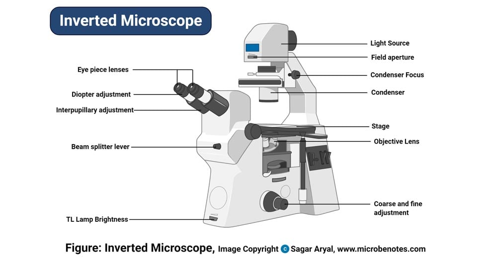
Inverted Microscope is a type of light microscope whose objective lenses and turret are below the stage, and the illuminator and condenser are above the stage. In this type, we have to look upward to see the specimen.
Its working principle and instrumentation are similar to a simple / compound / upright microscope, but the position of the light source, turret, objective lenses are inverted. In some digitalized types, the camera is fixed to take photos or videos of specimens.
Uses of Inverted Microscope
- Used in metallurgical processes for observing metals and minerals
- Used in cytology to study cell division process and observe minute living organisms
- Used in microbiology to detect M. tuberculosis, Phytopthora spp. in culture
Limitations of Inverted Microscope
- Very limited in number and expensive
- Thickness of slide or petri dish used to hold specimen affects in imaging
11. Acoustic Microscope
Acoustic Microscope is a type of microscope that uses a very high-frequency ultrasound wave instead of light or electrons to develop an enlarged image of an object. It uses sound waves to scan the specimen and the reflected sound is electronically processed to develop an image. Hence it is called acoustic. It uses ultrasonic audio, so it is also called Ultrasonic Microscope. Sound waves of 5 MHz to 400 MHz are generally used.
Acoustic Microscope Principle
The transducer converts the electric signal into ultrasonic sound. The sound waves are focused on the specimen using a coupling fluid. The sound hits the specimen and some waves get reflected and others get transmitted.
Imaging is done by two methods; Pulse-Echo mode and Transmission Mode. In Pulse-Echo mode, a single transducer is used and the amplitude, phase, and time of the return of the reflected sound (echo) are processed. While in Transmission Mode, two transducers are used. One receives a transmitted sound wave and another receives a reflected sound wave. In both methods, a sample is scanned pixel by pixel and a planar (2-D) image is developed.
Acoustic Microscope Parts
The main instrumentation used in an acoustic microscope is a transducer. It is a combination of a loudspeaker and microphone. It converts the electric signal into the ultrasonic wave and also re-transforms the received audio into an electric signal. Computer software then analyzes the received electric signal into an image. These types of microscopes have the capacity to view the internal structure of a specimen. Even a feature of submicron level is picked. It can protect sample integrity and obtain information about internal characters.
Uses of Acoustic Microscope
- Used mainly in quality control and production of electronic devices, imaging circuit boards, detecting cracks in microchips, etc.
- Used in chemical industry, pharmaceutical industry, ceramic industry, etc. for quality checking of products.
- Used in cytological and histological examination to study cells internal structures, cell motility, elasticity, etc.
Limitations of Acoustic Microscope
- Sound needs medium to travel
- It is difficult to manipulate sounds
- Slow processing time
- Expensive
12. X-Ray Microscope
X-Ray Microscope is a type of optical microscope that uses an X-rays beam to illuminate samples and produce their enlarged image. An X-ray can easily penetrate most of the objects, so it can be used to get images of any objects without any special preparations or staining. X-rays of energy 100 – 1,000 eV which corresponds to a wavelength of about 1 nm are generally used. Modern X-ray microscopes use X-rays of the wavelength of 0.1 to 10 nm.
X-Ray Microscope Principle
It is developed on the basis of the fact that when molecules of a matter interact with X-rays, they get ionized. The electrons of atoms of ionized molecules get excited to a higher energy state. The excited electrons return to their ground state emitting the excitation energy in form of X-rays. These emitted X-rays are of specific energy and wavelength corresponding to the characteristic of the element.
X-rays are produced in an X-ray tube and focused on the specimen for illumination of the specimen. When the high-energy X-rays hit the sample, some of it is scattered, some penetrate the sample and some get absorbed.
The molecules get ionized and the electrons get excited to a higher energy state. The excited sample emits the X-rays of a certain wavelength corresponding to the type of atoms in the specimen.
The image of the specimen is developed either by the photograph method or by the detector system. In photographs, method image is developed when the emitted X-ray hits on X-ray plate or phosphorescent plate. In a detector system, a Charged-coupled device or scintillator detector, or other X-ray detectors are used to detect the emitted x-ray and convert them to electrical signals. The electrical signals are processed by a computer and the image is developed on a monitor.
X-Ray Microscope Parts
- X-ray Tube
These are cathode ray tubes that produce X-rays. It includes a vacuum system containing metallic anode plates and a cathode. The cathode is generally tungsten filaments that produce electron beams when heated by high voltage electric current. The produced electrons are accelerated and bombarded on the surface of anode metal plates. While hitting the metal plate, electrons get suddenly decelerated releasing X-ray photons containing the energy corresponding to the striking electrons.
- Collimator
It is a device that focuses the produced X-rays into a parallel beam, and the process is called collimation. The collimator contains two sets of tightly packed metallic plates separated by a narrow gap of 0.5 micrometers or less. These plates absorb all the X-rays but allow a narrow beam to pass through the gap forming a collimated X-ray beam.
- Monochromator
It is an optical device used to polarize an unpolarized beam of X-ray. A monochromator may be either a filter that allows it to pass a certain wavelength and absorb all other unwanted radiation, or crystal (crystals of quartz, NaCl, LiF, etc.).
- Detection System
It includes detectors that detect the emitted X-rays for imaging. There are different types of detectors used;
- Imaging Detectors
This system uses photographic plates or X-ray film to detect the emitted X-rays. Phosphor plates, silver bromide, or silver halide plates are mostly used for developing X-ray images.
- Scintillator Detectors
It is comprised of a scintillator and photomultiplier tube. Scintillators commonly used are sodium iodide crystals activated with thallium. Others like crystals of naphthalene, terpineol, anthracene, etc are also used. These scintillators when get struck by X-rays emit visible light. These visible lights are detected by a photomultiplier tube and converted into electric pulses.
- Semiconductor Detectors
It uses silicon and lithium plates as semiconductors. When an X-ray hits the semiconductor, an electron and a hole are produced. Under influence of an electric field, these produced electrons and holes are swept and detected by special electronic devices. These electric signals are processed to produce images.
- Other detectors like Geiger-Muller tube, Proportional counter are also used in some types.
Uses of X-Ray Microscope
- Used for identification and characterization of crystals and polymers
- Used in metallurgy, petroleum, ceramics and glass manufacturing industries for quality control
- Used in geology to study rocks, minerals and soil composition
Limitations of X-Ray Microscope
- Difficulty in imaging
- Expensive, time consuming process and complex instrumentation
13. Polarizing Microscope
Polarizing Microscope is a special type of light microscope that uses polarized light to illuminate a specimen and develop its magnified image. It is similar to a regular optical microscope but uses polarized light instead of normal natural light. It enhances image quality and image contrast. They are also called petrographic microscopes.
Polarizing Microscope Principle
Normal light produced from illuminator is passed through polarizer which converts the normal light into plane-polarized light. The polarizing microscope focuses the plane-polarized light on anisotropic (substance having multiple refractive indexes) specimen. When the polarized light waves strike such anisotropic specimen, birefringence (double reflection) occurs generating two waves, ordinary and extraordinary waves, which are perpendicular to each other. These two waves get transmitted in different phases. An analyzer combines these two waves and passes through the ocular lens to develop an enlarged image.
Polarizing Microscope Parts
It contains all the parts of an ordinary light microscope and additionally few optical devices are added viz.:
- Polarizer
It is a filter that polarizes the unpolarized light generated by a light source. It is placed between the illuminator and specimen stages.
- Analyzer
It is another polarizing filter that is placed in an optical path above objective lenses.
- Accessory Plates
These include compensator and retardation plates. They determine optical path difference or relative retardation between ordinary and extraordinary waves produced during birefringence. These plates are produced before the analyzer. They produce more contrast in images and help to clearly visualize internal structures.
- Specialized Stage
Polarizing microscopes use a circular stage that can move in 360° directions.
Uses of Polarizing Microscope
- Used in geological studies to study rocks, minerals and soil components.
- Used is studying internal structures of transparent planktons, diatoms, protozoans, etc.
Limitations of Polarizing Microscope
- Require anisotropic specimen
- Have limited applications
14. Metallurgical Microscope
Metallurgical Microscope is a type of microscope that uses reflected light for observing metals to study their structure and organization. It is used to study metallography.
Its instrumentation and design are similar to an optical microscope. The only difference is that this microscope uses reflected light instead of transmitted light for imaging.
Its application is limited to the observation of metallic objects, alloys, rocks, ceramics, and other opaque objects.
15. Pocket Microscope
Pocket Microscope is a small portable microscope designed to carry easily. It is a simple microscope containing an eyepiece, LED as light source and battery for LED operation, a mirror, and a stage for sample holding. In some types, there is a camera for recording images digitally.
This is for general uses like observing jewelry, stones, watchmaking, electronics, insects, and other objects at size on millimeter-scale.
Since magnification is low, up to 100X, it can’t be used for observing microscopic samples like microorganisms and others.
16. USB Microscope
USB Microscope is a type of low-power digital microscope that is connected to the computer USB port. They use a digital camera with a high-power macro lens that can zoom in up to 200X.
Instrumentation is simple, containing a light source (LED), a digital camera, and a USB port to connect to the camera. Image is viewed on-screen of the computer. We can save images or videos and edit or process them using computer software.
This type of microscope generally uses reflected light. Working is simple. LED passes the light over the sample. Using a digital camera the reflected light is captured as an image and stored digitally in a computer to which it is linked via a USB port.
This type of microscope is used for observing insects, coins, gems, jewelry, small letters, scripts, crystals, etc. It is used in medical examination, endoscopy, and ENT examinations.
They are cheap and portable but have low magnification.
References
- Images created using biorender.com
- Microscopy: Intro to microscopes & how they work (article) | Khan Academy
- What is Microscopy? (with pictures) (infobloom.com)
- Microscopy and Types of Microscopy (brainkart.com)
- What is Microscopy? | The University of Edinburgh
- Microscope Glossary of Terms: Microscope A-Z – Microscope and Laboratory Equipment Reviews (microscopespot.com)
- Resolution | Nikon’s MicroscopyU
- What is Microscope Resolution? – Microscope Clarity
- How does a microscope work? – Explain that Stuff
- How does a Microscope work ? (microscopemaster.com)
- Anatomy of a Microscope – Microscope Illumination | Olympus LS (olympus-lifescience.com)
- KEYENCE America
- Types of Microscopes (cliffsnotes.com)
- Types of Microscopes: Definition, Working Principle, Diagram, Applications, FAQs (byjus.com)
- Fluorescence Microscopy – Principle, Components, Mechanism (noteshippo.com)
- Fluorescence Microscope: Principle, Types, Applications • Microbe Online
- https://www.olympus-lifescience.com/en/microscope-resource/primer/techniques/fluorescence/anatomy/fluoromicroanatomy/
- What is confocal microscopy ? | Cherry Biotech
- Fish K. N. (2009). Total internal reflection fluorescence (TIRF) microscopy. Current protocols in cytometry, Chapter 12, Unit12.18. https://doi.org/10.1002/0471142956.cy1218s50
- What Is an Electron Microscope (EM) and How Does It Work? – VHA Diagnostic Electron Microscopy Program (va.gov)
- Scanning-tunneling microscope – definition of Scanning-tunneling microscope by The Free Dictionary
- Dark-field Microscopy: Principle and Uses • Microbe Online
- What is Dark Field Microscopy – Microscope Clarity
- What is a Dissecting Microscope? (with picture) (wise-geek.com)
- Digital Microscopes | Products | Leica Microsystems (leica-microsystems.com)
- Scanning-probe-microscope Meaning | Best 1 Definitions of Scanning-probe-microscope (yourdictionary.com)
- Atomic force microscope Definition & Meaning – Merriam-Webster
- Atomic Force Microscope (AFM) – Definition, Principle, Application (microbiologynote.com)
- What is an Inverted Microscope – Microscope Clarity
- Acoustic Microscope – Technology Transducer (ksisam.com)
- Acoustic Microscopy – Benefits, Limitations and Uses (microscopemaster.com)
- X-Ray Spectroscopy Principle, Instrumentation and Applications (microbiologynote.com)
- What is a Polarizing Microscope? (with picture) (wise-geek.com)
- Jacobsen, C. (2019). Index. In X-ray Microscopy (Advances in Microscopy and Microanalysis, pp. 573-579). Cambridge: Cambridge University Press.
- Principle, Instrumentation, Types and Applications of XRD (14impressions.in)
- Molecular Expressions Microscopy Primer: Specialized Microscopy Techniques – Polarized Light Microscopy – Compensators and Retardation Plates (fsu.edu)
- How do Polarized Light Microscopes Work? (azolifesciences.com)
- What Is a Metallurgical Microscope? (wise-geek.com)
- Metallurgical microscope (slideshare.net)
- Metallurgical Microscope Information (microscopeworld.com)
- What is a Pocket Microscope? (wisegeek.net)
- microscope | Types, Parts, History, Diagram, & Facts | BritannicaParts of the Microscope with Labeling (also Free Printouts) – Laboratoryinfo.com
- Parts of a Microscope and their function (microbiologynote.com)
- Parts of a Microscope – The Comprehensive Guide – Microscope and Laboratory Equipment Reviews (microscopespot.com)
- Microscope: Definition, Types, Uses, Parts & Examples | Toppr
- Simple Microscope Definition, Magnification, Parts And Uses (byjus.com)
- Phase Contrast Microscope – Definition, Principle, Parts, Uses (learninsta.com)
- What is Fluorescence Microscopy? Definition, Principle, Fluorescence & Parts – Biology Reader
- Electron Microscope: Definition, Types, Parts, Application, Advantages, Disadvantages (microbiologynote.com)
- DARK FIELD MICROSCOPE: CHARACTERISTICS, PARTS, FUNCTIONS – SCIENCE (warbletoncouncil.org)
- Dissecting Stereo Microscope Parts and Functions (microscopemaster.com)
- Confocal Microscope Principle, Uses, Parts, Advantages, and Disadvantages. (microbiologynote.com)
- Inverted microscope Images and definition, principle, Uses, Parts. (microbiologynote.com)
- USB Microscope- definition, principle, parts, examples, uses.docx – USB Microscope- definition, principle, parts, examples, uses March 26, 2020 by Faith | Course Hero

It good to used media for studies because its has easy note for student.
A comprehensive and crisp guide for my labratory work and knowledge
The best information platform
Happy to meet this website